Pipe Inspection Robots
Over 10+ years the Robotics Research Institute at UTS held contracts with Sydney Water, the major NSW water utility in charge of over 20000km of pipelines. A significant portion of these networks are old (100yrs+) and made from cast iron. With exposure to water/chemicals and long-age, corrosion is a re-occurring problems across the industry. As pipes corrode, they weaken and burst. Existing tools and technology exist for scanning pipes, however there are major cons (disruptive, expensive). These projects were aimed at assessing all available options and ultimately designing a custom solution.
System Design
Prototypes have been produced for different pipe environments (water/sewer) and other factors such as pipe diameter. They all utilise a custom kevlar shielded 2 core communication tether with onboard power, and a made to purpose reel that automatically handles cable layering and measuring travel distance.
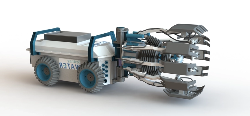
Sewer rising inspection robot - designed for pipes between 450-900m diameter. 12 electro-magnetic sensors. 2 cameras.
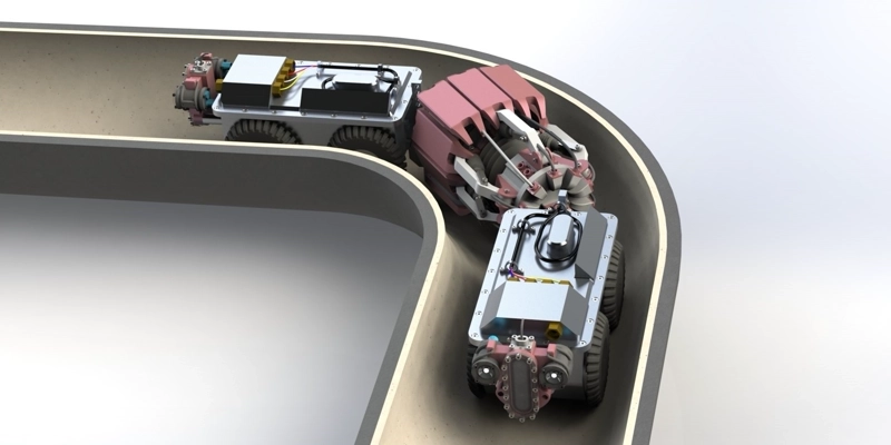
Sewer rising inspection robot - designed for pipes between 250-450mm diameter. 12 electro-magnetic sensors. 2 cameras.
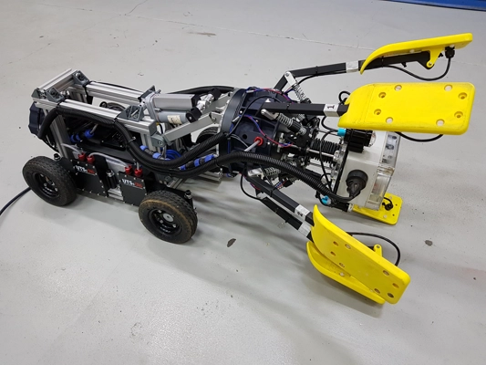
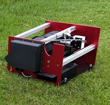
Early prototype for the water mains pipe, still using slotted aluminium channels for quick assembly and modification while testing.
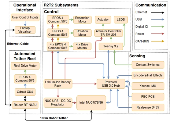
System diagram for the onboard components and their connections.
Image of the finish on the motor housing plates. These units were stand-alone and IP68 rated for operation in wet pipes.
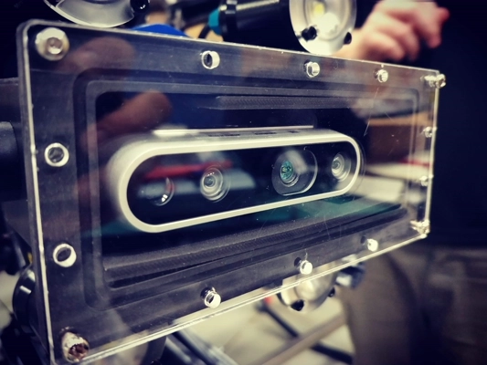
Realsense camera giving both RGB for inspection and operator feedback, and depth data used for 3D mapping the network.
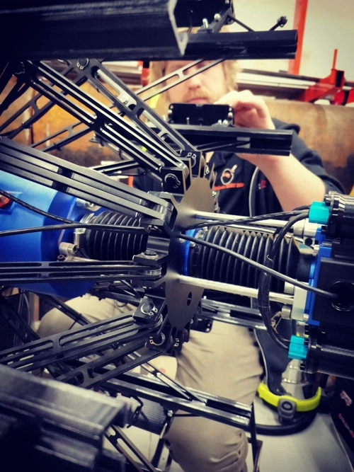
Scissor style mechanism allowing sensors to expand over a wide range of diameters, built in spring tension to bring the sensors back in if power / control failure.
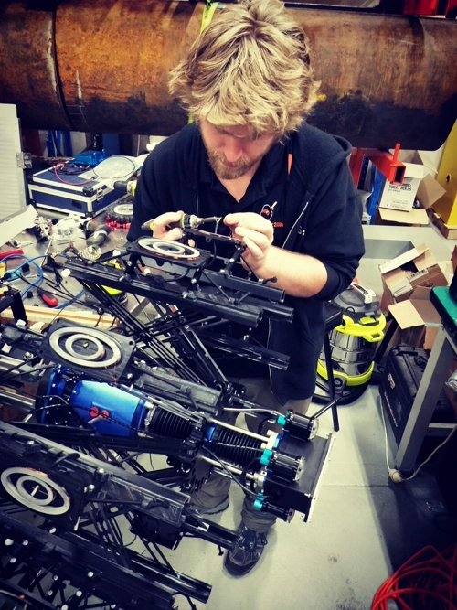
Soldering up the electro-magnetic sensors coils.
Communication reel that featured automated layering with a self-reversing lead screw, fixed tension management and velocity control based on robot movement and network management between operator PC, by-stander phone preview and robot on-board PC.
Electrical
Two primary electrical designs were required for many of the prototype pipe robots. A pulsed eddy current sensor board and core system interface PCB. These went through numerous iterations, with many variations for the different robots required to suit changing pipe sizes and necessary mechanical/power/thermal specifications.
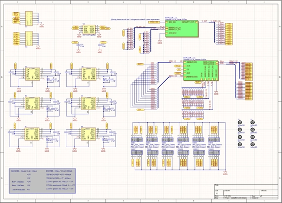
Pulsed eddy current schematic showing the driving and receiving circuitry, with power and connectors.
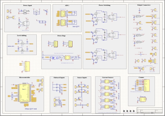
Core system PCB, handling power rails control and monitoring, sensor input, voltage regulation and motor control.
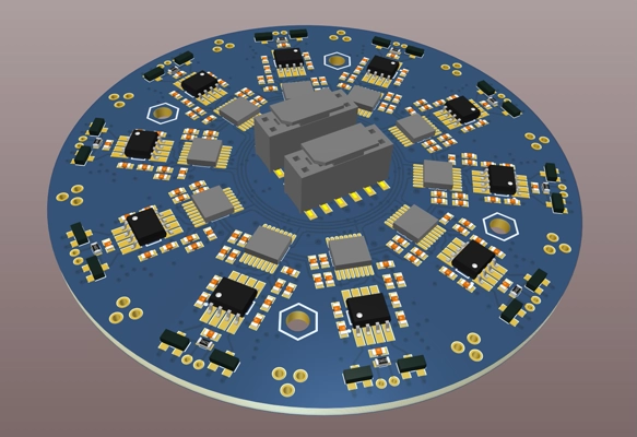
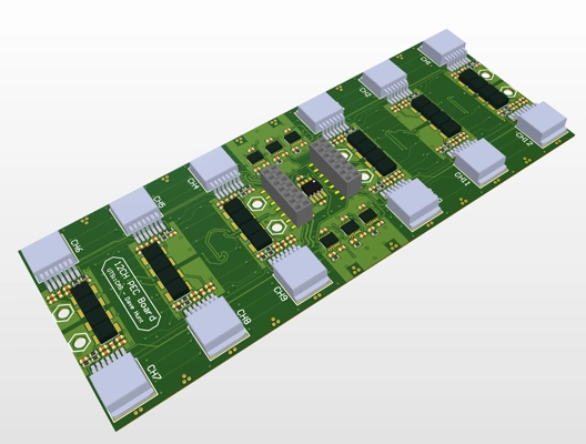
8-layer PCB with 10 channels stacked pulsed eddy current board. Optimised to minimise noise interference from switching power regs, and thermal management in a minimal space enclosure.
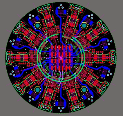
Complex routing of 8-layer 10 channel electro-magnetic PCB.
Pulsed eddy current sensors driver PCBs. Each of the 12 parallel channels fire using an op-amp (OP548T). The decay curves are measured using instrumentation amplifier into a 16-bit ADC. The 12 ADC channels are all daisy chained together using SPI.
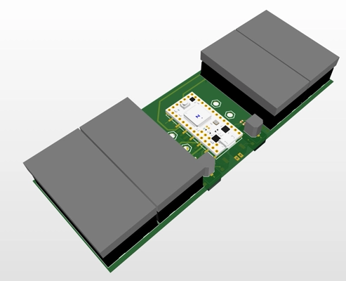
Stackable power module for driving of the sensor PCBs. Integrate Teensy for optimal control and sensor scraping.
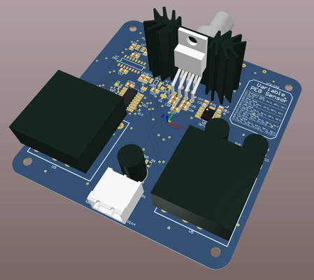
Experimental PCB with numerous driving and receiving circuitry, designed to discover optimal method.
Software
Assortment of software images.
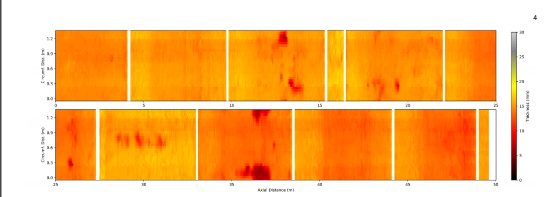
Real-time thickness map showing an unrolled pipe. This 50m length demonstrates the isolated pitting that can be found.
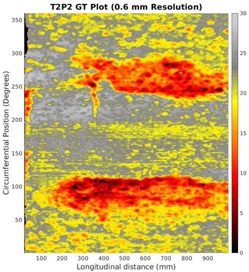
High resolution thickness map providing comparison the ground truth for accuracy estimation of thickness scanning technique.
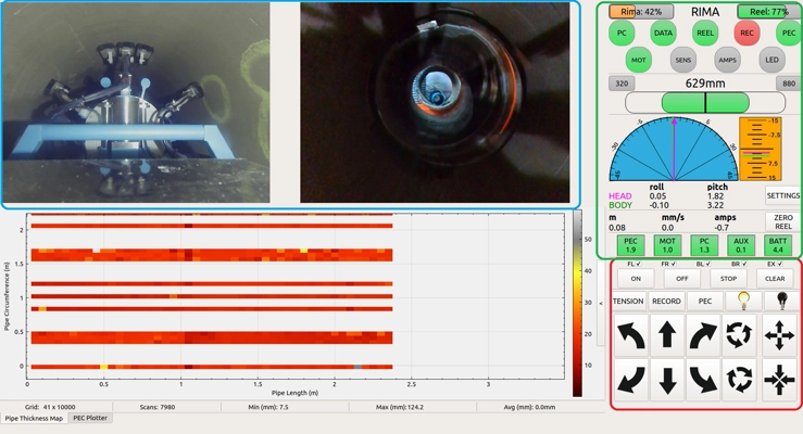
User interface for the real-time operation of several pipeline robots. Features include multiple camera feeds (switchable angles), system status and value readouts, online thickness map generator and robot controls.